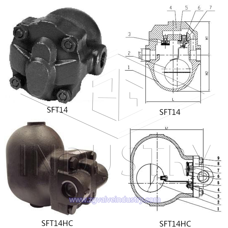
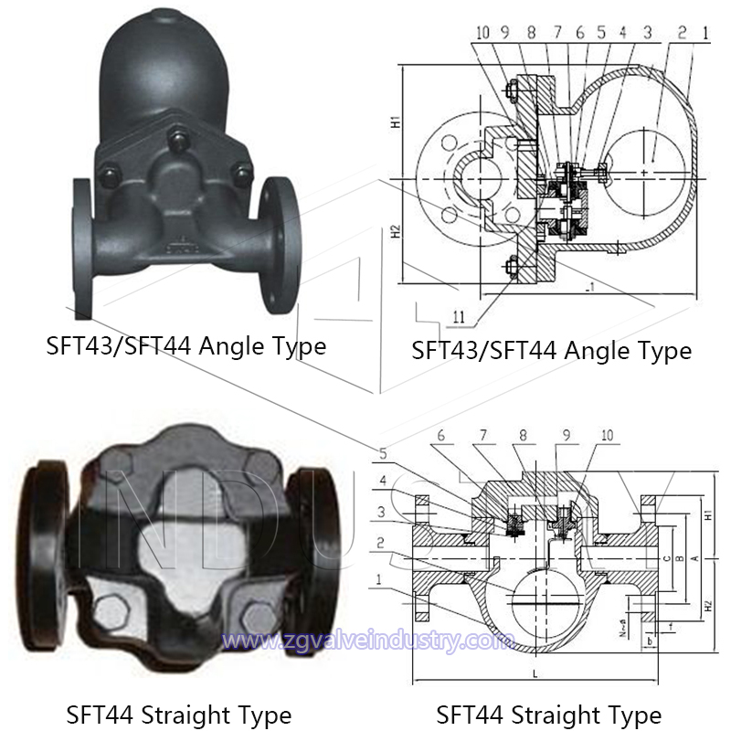
Design Features:
The biggest advantage of the lever float type steam trap is that it is not affected by the fluctuation of pressure, temperature, and condensate flow. It drains continuously and drains when there is water. The minimum subcooling degree is 0℃, which can make the heating equipment achieve the best working efficiency.
The valve seat of the lever float steam trap is always below the liquid level to form a water seal without steam leakage; its minimum working pressure is 0.01Mpa, and the maximum back pressure rate is ≤85%; there is an exhaust device inside, and the lever float The steam trap adopts the most advanced diaphragm element as the automatic air exhaust valve, which can automatically remove non-condensed gas, is very sensitive, has high working quality and long service life.
The trap is designed with a balanced double valve seat structure, which can achieve a small volume and a large displacement. It is especially suitable for steam barrier drainage of large heating equipment and heat exchange station equipment. It is the first choice for steam traps for large heating equipment.
Field of Application:
Size Range: 1/2"-6"/DN15-DN250
Temperature: ≤425℃
Allowable Operating Pressure:PN16/PN25/PN40
Scope of application of trap: Purpose: steam pipeline, steam equipment, heating pipeline, heating pipeline, condensate pipeline.


MATERIAL LIST
| Part Name | Specification |
| Body | ASTM A216 WCB |
| Bolt | 2Cr13 |
| Bracket | 2Cr13 |
| Seat | S.S 304 |
| Ball Float | S.S 304 |
| Disc | S.S 304 |
| Gasket | Graphite |
| Bonnet | ASTM A216 WCB |
| Air Vent | Hastelloy |
| Lever | S.S 304 |
Dimensions (mm)
| Model |
Size |
DN |
Connection Type |
Maximum Allowable Temperature |
Dimensions |
Weight(KG) |
| L |
H1 |
H2 |
| SFT14 |
1/2", 3/4" |
15/20 |
Threaded End NPT/BSP |
≤425℃ |
125 |
85 |
65 |
3.4 |
| SFT14 |
1" |
25 |
Threaded End NPT/BSP |
≤425℃ |
145 |
95 |
70 |
4.25 |
| SFT14 |
11/4",11/2",2" |
32/40/50 |
Threaded End NPT/BSP |
≤425℃ |
250 |
150 |
100 |
24 |
| SFT14HC |
1/2", 3/4" |
15/20 |
Threaded End NPT/BSP |
≤425℃ |
120 |
115 |
80 |
7 |
| SFT14HC |
1" |
25 |
Threaded End NPT/BSP |
≤425℃ |
120 |
115 |
80 |
7.6 |
| SFT44 |
1/2", 3/4" |
15/20 |
Flanged End
(DIN,JIS,ANSI) |
≤425℃ |
170 |
85 |
65 |
5.2 |
| SFT44 |
1" |
25 |
Flanged End
(DIN,JIS,ANSI) |
≤425℃ |
190 |
95 |
70 |
6 |
| SFT43 |
1/2", 3/4" |
15/20 |
Flanged End
(DIN,JIS,ANSI) |
≤425℃ |
150 |
105 |
80 |
19 |
| SFT43 |
1" |
25 |
Flanged End
(DIN,JIS,ANSI) |
≤425℃ |
160 |
105 |
85 |
22 |
| SFT43 |
1-1/4" |
32 |
Flanged End
(DIN,JIS,ANSI) |
≤425℃ |
230 |
130 |
125 |
28 |
| SFT43 |
1-1/2" |
40 |
Flanged End
(DIN,JIS,ANSI) |
≤425℃ |
230 |
130 |
125 |
29 |
| SFT43 |
2" |
50 |
Flanged End
(DIN,JIS,ANSI) |
≤425℃ |
230 |
130 |
125 |
31 |
| SFT43 |
2-1/2“ |
65 |
Flanged End
(DIN,JIS,ANSI) |
≤425℃ |
320 |
150 |
100 |
/ |
| SFT43 |
3” |
80 |
Flanged End
(DIN,JIS,ANSI) |
≤425℃ |
320 |
150 |
100 |
/ |
| SFT43 |
4“ |
100 |
Flanged End
(DIN,JIS,ANSI) |
≤425℃ |
320 |
150 |
100 |
/ |
| SFT43 |
2-1/2“ |
65 |
Flanged End
(DIN,JIS,ANSI) |
≤425℃ |
450 |
240 |
175 |
/ |
| SFT43 |
3” |
80 |
Flanged End
(DIN,JIS,ANSI) |
≤425℃ |
450 |
240 |
175 |
/ |
| SFT43 |
4“ |
100 |
Flanged End
(DIN,JIS,ANSI) |
≤425℃ |
450 |
240 |
175 |
/ |


