This butterfly valve is suitable for petroleum, chemical, food, medicine, papermaking, water and electricity, water supply and drainage, refining, energy and other system pipelines. This type of butterfly valve can be used as regulating and shut-off equipment on various corrosive and non-corrosive gas, liquid, semi-fluid and solid powder pipelines and containers. This butterfly valve is widely used in high-rise building fire protection systems and other pipeline systems that need to display valve switch status.
Design Features:
1. Small and light, easy to disassemble and maintain, and can be installed in any position.
2. Simple structure, compact 90° operation, quick opening and closing.
3. Small operating torque, labor-saving and lightweight.
4. To achieve complete sealing, the gas test leakage is zero.
5. Choose different parts and materials, which can be applied to a variety of media.
6. The flow characteristics tend to be straight, and the adjustment performance is good.
7. The number of opening and closing tests is up to tens of thousands, and it is ordered to be long.
8. All pipelines using gate valves, globe valves, cocks, hose valves and diaphragm valves, especially in high-rise building fire protection systems and pipeline systems that need to display the valve switch status, can be replaced with this valve.
Working Principle
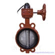
1. The signal butterfly valve is driven by the worm gear and worm drive to rotate the shaft and the butterfly plate to open and close and control the flow.
2. Rotate the hand wheel of the worm gear and worm drive to make the butterfly plate open and close and adjust the flow. The hand wheel is clockwise to close the valve.
3. There are two types of micro switches in the worm gear box:
(1) There are two micro switches for opening and closing in the transmission box, which act respectively when the valve is fully open and fully closed, and turn on the power supply of the "valve open" and "valve close" indicator lights in the control room. , so that it can accurately display the valve switch status.
(2) In the transmission box, there is only a micro-movement opening in the closing direction (the full-close position of the butterfly plate is 0°). When the butterfly plate is in the position of 0-45°, the micro-switch acts and outputs the valve closing signal. At 45-90° position, another pair of normally closed contacts can output the valve opening signal. The cam bundle can be micro-switched at high speed to display the different positions of the butterfly plate.
Field of Application:
Operating Temperature:
NBR: 0℃~+90℃
EPDM: - 20℃~+120℃
PTFE: -10℃~+150℃
Operate:
DN50-DN250: Lever
DN300-1200: Worm gear
Optional operation: Lever, Worm gear, Pneumatic, Electric-Motorized
Application: Chemical processing, Desalination plants, Drinking water, Dry powder, Food and beverage, Gas plants, HAVC Mining industry, Paper industry, Sand handling, Seawater, Sugar industry, Thermo technical water treatment, Waste water, Cooling Water Circulation, Compressed Air
Technical Specification:
Design Standard:
EN 593, MSS SP67, API 609, BS5155
Face to Face dimension:
ISO 5752, EN 558, MSS SP67, API 609, DIN3202
End Standard:
ANSI B16.1 Class125LB & B16.5 Class150LB
AS 2129 Table D & E BS 10 Table D & E
DIN 2501 PN6, PN10 & PN16
EN 1092 PN6, PN10 & PN16
ISO 2531 PN6, PN10 & PN16
ISO 7005 PN6, PN10 & PN16
KS B 1511 / JIS B 2210 5K & 10K
MSS SP44 CL. 150LB AWWA C207
SABS 1123 Table 1000/3 & Table 1600/3
Top Flange: ISO5211
Test standard: API 598, ISO 5208, EN 12266

MATERIAL LIST
| Material Specification |
| Part Name | Material |
| Body | Cast Iron, Ductile iron, WCB, SS304, SS316, Bronze, Aluminum Alloy |
| Seat | EPDM, NBR, PTFE, VITON, Rubber |
| Dsic | Ductile Iron, CF8, CF8M, WCB, Bronze, Aluminum Alloy
|
| Stem | 45#, 410, 420, 431, 304, 304L, 316, 316L, Bronze, Monel, Hard alloy |