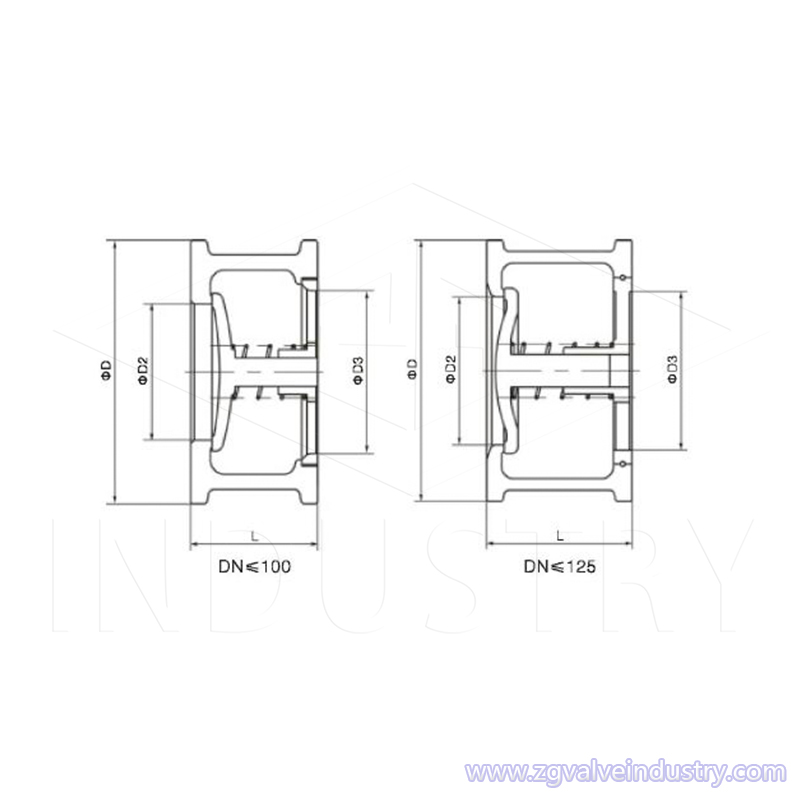
Design Features:
Check Valves are the valves of stopping the fluid from backflow. The disc can be opened by the pressure of fluid. And then the fluid runs from the inlet to the outlet side. When the pressure of inlet is less than outlet, the disc can be cloased automatically and stop the fluid from backflow.
1. Lifting steel check valve has the advantages of simple structure, reliable action and convenient maintenance. It is widely used in purification equipment, petroleum, chemical industry, metallurgy, electric power, textile and other production processes.
2. When the medium flows into the valve body from the direction indicated by the arrow of the valve body, the pressure of the medium acts on the valve clack to produce an upward thrust. When the medium thrust is greater than the weight of the valve clack, the valve opens. When the pressure of the medium behind the valve acts on the disc and the weight of the disc itself is greater than the force exerted on the disc by the pressure in front of the valve, the valve is closed to prevent the medium from flowing back.
3. The function of the lift check valve is to only allow the medium to flow in one direction and prevent the reverse flow. Moreover, the valve clack can be made of metal, or can be inlaid with leather, rubber, or synthetic covering, which can be selected flexibly.
4. The valve disc of the lift check valve is seated on the sealing surface of the valve seat on the valve body. Except that the disc can be lifted and lowered freely, the rest is like a shut-off valve. The fluid pressure lifts the disc from the sealing surface of the valve seat, and the backflow of the medium causes the disc to fall back to the valve seat and cut off the flow.
It is suitable for clean media, not for media containing solid particles and high viscosity.
Wafer Single Flap Lift Check Valve Features:
1.Water hammer pressure:
very small, short disc stroke, spring assisted closing, fast valve closing speed
2. Dimensions and weight:
The structure length of the wafer single flap lift check valve is only 1/4~1/8 of the flange lift check valve, and the weight is only 1/7~1/20 of the flange lift check valve.
The structure is very short in length, small in size, and light in weight, which brings great convenience to the installation, transportation, storage and pipeline arrangement of the valve, and can save a lot of materials and reduce the cost.
3. Fluid resistance
Larger, the fluid resistance coefficient is 2.8~6.4
Still smaller than the fluid resistance coefficient of the flange lift check valve (6~12)
4. Installation method
It can be installed horizontally or vertically, with light weight and easy installation.
5. Cracking pressure
Very small, the disc can fully open the valve under a small pressure difference.
6. Reliability
The valve is a whole structure, simple and compact, the impact force is small when the valve is closed, the water hammer pressure is very small, the valve life is long, and the reliability is high.
Field of Application:
Size Range: 1/2"~8" DN15-DN200
Working Pressure: PN10~PN100
Working Temperature: -196~540°C
Application for: By selecting different materials, it can be applied to a variety of media such as water, steam, oil, nitric acid, acetic acid, strong oxidizing media, and urea.
Technical Specification:
Design standard: JB/T8937
Face to Face dimension: JB/T8937
Connection flange: JB/T74-90, GB/T13402, GB/T9112-9124, HG/T20592~20635
Pressure temperature rating: JB/T74, GB/T9124, HG20604~20625
Test standard: JB/T9092

MATERIAL LIST
| Material Specification |
| Part Name | Material |
| Body | WCB, A105, WC6, F11, WC9, F22, LCB, LF2, CF8, F304, CF3, F304L, CF8M, F316, CF3M, F316L, ZG1Cr18Ni9Ti, 1Cr18Ni9Ti, ZG1Cr18Ni12Mo2Ti, 1Cr18Ni12Mo2Ti, Copper and copper alloys, Ti and Ti alloys |
| Trim | 304, 304L, 316, 316L, SS321, Alloy 20, Copper and copper alloys, Ti and Ti alloys |
| Spring | 304, 304L, 316, 316L, Monel, Inconel600, incomel X-750 |
| Seal | 13Cr/13Cr, body material, Stainless Steel, Monel alloy, Cemented carbide, Alloy 20(N08020), Copper and copper alloys, Ti and Ti alloys, NBR, PTFE, VITON, EPDM, Silicone rubber |


